Roof Framing Simplified
This direct approach involves full-size layouts and stringing rafter lines

There isn’t a cut in roof framing that can’t be calculated given a sharp pencil, a framing square and a head for math. But my 20 years in the trade have taught me that in some cases, the theoretical calculation of rafter angles and lengths is slower and leaves more room for error. While I think that it’s important to under- stand the geometry of roof framing, the empirical method can save time and frustration, and contribute to your understanding of the pro- cess. I’m better at solving problems when I can grasp them—literally.
When I’m cutting a complicated roof and things get foggy, I use two techniques to help me produce rafters that fit the first time. I chalk lines on the plywood subfloor to represent a rafter pair in relation to its plates and ridge. This two-dimensional diagram is laid out full size. Pattern rafters can be tested right there on the job site. The other method I use is to deal di- rectly with the components involved by getting up on the roof and measuring the relationships between the rafter to be cut and the existing plate and ridge with string and sliding bevel.
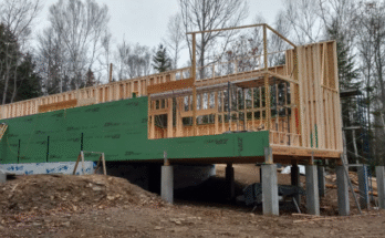
I used this method several years ago when I built a Y-shaped house. One wing was for the bedrooms and the other contained the kitchen, dining room and family room. The stem of the Y was the living room. The roof over the wings called for trusses, but the living-room rafters were exposed. The problem was in framing the intersection of the three roofs. These beams were big, long and expensive, and all the cuts would show. Had the house been a T shape, the valley rafters would have been a textbook case, and I could have found the information I needed in the rafter tables on my framing square. But since the intersection was 120° and not 90°, I had to find the angles by calculation or direct observation. I chose the latter.
Full-size layout—After setting the trusses, I chalked a full-size layout of the living-room common rafters and ridge on the subfloor be- low. The ridge beam was a 4×14, and the com- mon rafters were 4x8s on 4-ft. centers. I de- cided to tackle the easiest steps first. This gave me time to think about the problem while re- ducing the parts in the puzzle. The ridge beam went up first. I found its height by measuring on the full-size layout.
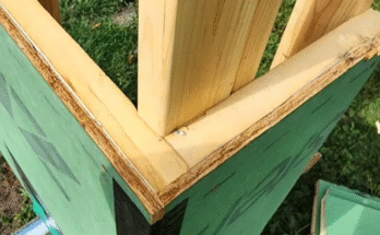
The common rafters were then cut using patterns made from the layout. I nailed these in place starting at the outside wall, working toward the junction of the Y. The valley rafter was next. Its location is shown above. Valley rafters are usually heftier than common rafters because they have a longer span, and have to carry the additional weight of the valley jacks. In this case, the valley rafter was a 4×10. Because it’s deeper, to achieve the same height above the plate and ridge, its seat and ridge cuts also differed from those of the common rafters. I found it faster and easier to measure the actual distances than to calculate imaginary ones. This way I could find the length of the rafter and the angles of the cuts without guesswork or error. This took me back up on the roof armed with a ball of nylon string, a sliding bevel and a level.
String lines—First, I tacked a scrap piece of wood vertically on the opposite side of the ridge beam from its intersection with the valley rafter. Then I tacked another block on the out- side of the top plate where the valley rafter would sit. Between these sticks, I stretched nylon string at the height of the top of the rafter and along its imaginary center line. The string made it easy to visualize the actual rafter in place. For reassurance, I sighted across the rafter tops from the outside wall to check the alignment. I used the sliding bevel and level to find the angle of all the cuts, being careful not to distort the string.
Before I transferred the angles to the rafter stock, I made two templates (called layout tees) for marking out the ridge cut and rafter seats. I made one for the bottom and one for the top of the valley rafter. With some adjustments, they fit when the center line drawn on the pattern was in line with the string representing the center of the rafter. The tees also allow you to test- fit the bird’s mouth to the plate before you carve up costly rafter stock. With these pattern pieces tacked in place, I measured the length of the valley directly. Then I transferred this length and the angles on the tees to the valley- rafter stock, and cut it to its finished dimensions. It fit perfectly the first time.
With the valley rafter in place, I turned to the valley jacks. First I made another pattern, this time of the ridge cut of the common rafter. I tacked it on the layout mark on the ridge and stretched the nylon line from it to the valley rafter, being careful to keep it exactly parallel to the common rafters. With the line simulating the top center line of the longest jack, I used the sliding bevel to find the angles of the plumb and side cuts. This time I transferred the angles directly onto the stock and cut it with a hand- saw. Each shorter jack was worked in the same way, using the nylon line to find the location and length; the angles remained constant.
Laying out rafters with a framing square is something I do a lot. However, in situations that call for unusual intersections with com- pound angles, I spend my time dealing directly with the problem. This reduces confusion and allows me to concentrate on the work.

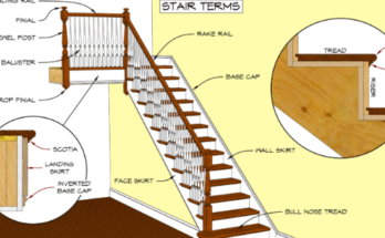
The names of the roof members (above), and the rafter terms (defined below) vary according to geographical region and roof style.
Span—the horizontal distance between the outside edges of the top plates.
Rise—the vertical distance measured from the wall’s top plate to the intersection of the pitch line and the center of the ridge.
Run—the horizontal distance between the outside edge of the top plate and the center of the ridge; in most cases, half the span.

Slope—a measurement of the incline of a roof, the ratio of rise to run. It is typically expressed using 12 as the constant run.
Pitch—has become synonymous with slope in modern trade parlance. It is actually the ratio of the rise to the span. A roof with a 24-ft. span and a rise of 8 ft. has a 1-to-3 pitch. Its slope is 8 in 12. Two ways of saying the same thing.
Unit rise—the number of inches of rise per foot of run.
Unit run—this distance is always 12 in.
Common difference—the difference between the length of a jack rafter and its nearest neighboring jack on a regular hip or valley when they are spaced evenly. This is also the same measurement as the length of the first, or shortest, jack.
Rafter pattern—a full-scale rafter template used to mark the other rafters for cutting. It can be tried in place for fit before cutting all the rafters.
Layout tee—a short template cut from the same stock as the rafters and used for scribing repetitive plumb cuts, tail cuts and bird’s mouths.
Tail—the part of a rafter that extends beyond the heel cut of a bird’s mouth to form the overhang or eave.
Pitch line—an imaginary line, also called the measuring line, that runs parallel to the rafter edges at the height of the full depth of the heel cut on the bird’s mouth. In common practice, rafters are measured along their bottom edge.
Theoretical length—the length of a rafter without making allowances for the tail or ridge reduction. Also called the unadjusted length.

Bird’s mouth—also called a rafter seat. It is the notch cut in a rafter that lets it sit on the double plate. It is formed by the plumb heel cut and the seat cut, which is a level line.
Plumb cut—any cut that is vertical when the rafter is in position on the roof. Also used as a reference to the top cut on a rafter where it meets the ridgeboard.
Level cut—any cut that is horizontal when the rafter is in position on the roof.
Tail cut—the cut at the outer end of the rafter. If cut at the outside edge of the double plate, it is a flush cut. All the other traditional tail cuts let the rafter overhang the plates—heel cut (level), plumb cut (vertical), square cut (perpendicular to the length of the rafter) or combination level and plumb cuts.
Side cut—also called a cheek cut, is the compound angle required for the proper fitting of roof members that meet in an intersection of less than 90°, and other than level. This applies to jacks that connect with hips and valleys.
Ridge reduction—rafter lengths are calculated to the center of the ridge of the roof. This doesn’t take into account the thickness of the ridgeboard. This allowance reduces the theoretical length of the rafter by one-half the thickness of the ridgeboard. The layout line drawn parallel to the plumb cut that represents this allowance is called the shortening line.
Dropping a hip—the amount by which the bird’s mouth on a hip rafter must be deepened to allow the top of the rafter to lie in the same plane as the jack and common rafters. This ensures that the roof sheathing will nail flat without having to bevel the top edges of the hip, a process known as backing.
Some additional pictures that could be helpful: