In the intricate dance of construction, where vision transforms into tangible reality, few documents are as fundamentally critical yet often underappreciated as the roof framing plan. Precisely as its title states, it is a scaled layout or diagram – a meticulously crafted technical drawing – that details the proposed roof development for a building. Far more than a simple sketch, it serves as the essential three-dimensional roadmap guiding the creation of the skeletal framework that will support the roof covering, withstand environmental forces, and define the ceiling space below. Understanding its components, purpose, and creation process is vital for architects, engineers, contractors, framers, and inspectors alike.

Beyond the Title: The Essence of the Plan
At its core, a roof framing plan is a specialized architectural or structural engineering drawing. It typically appears within the structural drawing set or as part of the architectural plans. The “scaled” aspect is paramount: every line, dimension, and symbol represents a physical element at a specific, reduced ratio (e.g., 1/4″ = 1′-0″), ensuring accurate translation from paper to building site. The “diagram” component implies it uses standardized symbols, notes, and conventions to communicate complex structural relationships efficiently.

Its primary function is to convey exactly how the roof structure is to be built. This includes:
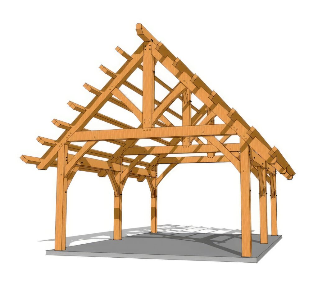
- Overall Geometry & Shape: Does the roof pitch steeply or gently? Is it a simple gable, a complex hip with valleys, a gambrel, mansard, or shed? The plan outlines the footprint and the slopes from every angle.
- Component Identification & Location: It precisely locates and labels every major structural member:
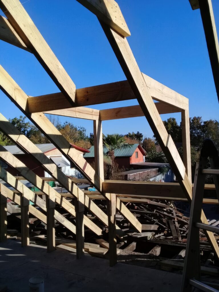
- Rafters/Trusses: The primary sloping members. The plan shows their direction, spacing (e.g., 16″ or 24″ on center), size (e.g., 2×10, TJI 360), and type (common, hip, valley, jack). For trusses, it often references separate truss design drawings (TDDs).
- Ridge Beams/Boards: The horizontal member at the peak where rafters meet. Size, species, and support points are specified.
- Hips & Valleys: The diagonal members forming the intersections of roof planes. Their size and connection details are crucial.
- Ceiling Joists/Collars Ties: Horizontal members connecting opposing rafters/trusses at their bottom or mid-height, resisting outward thrust and forming the ceiling structure. Spacing, size, and connections are shown.
- Supports: Beams (headers, girders), load-bearing walls, posts, and columns that transfer the roof load down to the foundation. Their locations, sizes, and bearing points are clearly indicated.
- Overhangs/Eaves: The projection of the roof beyond the exterior walls, detailing fascia and soffit framing members (lookouts, blocking).
- Openings: Locations and framing details for chimneys, skylights, vents, and dormers, including necessary headers and trimmers.
- Dimensions: Critical distances are annotated: overall building dimensions, wall locations, rafter/truss spacing, overhang lengths, distances between supports, and sizes of openings.
- Load Path: While not always explicitly drawn as a line, the plan inherently defines the path that roof loads (dead load – weight of materials; live load – snow, workers; environmental load – wind, seismic) will take from the roof surface, through the framing members, down to the supports, and ultimately to the foundation. This is the essence of structural integrity.
- Materials & Specifications: Notes specify lumber species and grades (e.g., #2 Southern Pine), engineered wood product types (LVL, PSL, LSL, I-joists), connector types (hurricane ties, joist hangers), fasteners (nails, screws – size and spacing), and any special treatment requirements.
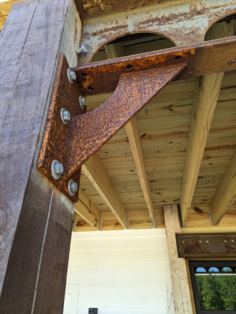
- Connections: Details or references indicate how members join together (e.g., birdsmouth cuts on rafters, specific nailing patterns, required metal connectors).

The Purpose: Why This Scaled Diagram is Indispensable
The roof framing plan is not merely an administrative requirement; it is the cornerstone of a safe, efficient, and code-compliant roof structure:
- Construction Blueprint: It is the primary guide for the framing crew. Without it, construction becomes guesswork, leading to errors, delays, and potential structural hazards. It tells them what to build, where to build it, how to build it, and with what.
- Structural Integrity & Safety: By defining member sizes, spacing, connections, and the load path, the plan (based on engineering calculations) ensures the roof can safely support all anticipated loads over its lifespan, preventing catastrophic failures like collapses.
- Coordination & Clash Detection: Created alongside other plans (floor plans, sections, elevations, MEP – Mechanical, Electrical, Plumbing), it helps identify potential conflicts before construction (e.g., a large HVAC duct running where a critical truss web needs to be).
- Material Estimation & Ordering: Accurate take-offs for lumber, trusses, connectors, and hardware rely entirely on the details provided in the framing plan. This prevents costly shortages or wasteful over-ordering.
- Cost Estimation: Contractors use the plan to accurately estimate the labor and materials required for the roof structure.
- Regulatory Approval: Building departments require roof framing plans (often stamped by a licensed engineer) to verify compliance with building codes (e.g., International Residential Code – IRC, International Building Code – IBC) regarding structural safety, wind resistance, snow loads, and seismic design.
- Communication: It serves as the universal language between the design team (architect, engineer), the builder, subcontractors (especially truss manufacturers), and the building inspector. Everyone works from the same definitive source.
- Future Reference: For renovations, repairs, or additions years later, the original framing plan is invaluable for understanding the existing structure.
The Creation Process: From Concept to Scaled Diagram
Developing an accurate roof framing plan is a collaborative and iterative process:
- Architectural Input: The architect’s design establishes the roof form, slopes, ceiling heights, aesthetics, and spatial requirements. Initial roof plans in the architectural set show the basic shape and major features.
- Structural Engineering: The structural engineer takes the architectural intent and performs calculations based on:
- Building location (governing wind speed, snow load, seismic zone)
- Building use and occupancy (affecting live loads)
- Span distances between supports
- Roof covering weight
- Applicable building codes
This determines the required sizes, species, grades, and spacing for all framing members and the necessary connections. For complex roofs or truss systems, specialized engineering software is often used.
- Drafting/Detailing: Using CAD (Computer-Aided Design) software like AutoCAD or Revit, or BIM (Building Information Modeling) platforms, a drafter or engineer creates the scaled plan. This involves:
- Drawing the building footprint to scale.
- Laying out the primary structural members (beams, ridge, bearing walls).
- Adding rafters/trusses with correct spacing and direction.
- Detailing hips, valleys, dormers, and openings.
- Dimensioning everything precisely.
- Adding all necessary notes, symbols, labels, and references to details or specifications.
- Cross-referencing related sections and details.
- Coordination: The draft plan is checked against architectural, mechanical, and electrical plans to resolve conflicts.
- Review & Approval: The engineer reviews and stamps the final plan, taking legal responsibility for its structural adequacy. The architect may also review for design intent.
- Truss Design (If Applicable): If prefabricated trusses are used, the framing plan provides key layout and support info. A separate, highly detailed Truss Design Drawing (TDD), created by the truss manufacturer’s engineer, is then generated specifically for fabrication.
Conclusion: More Than Lines on Paper
A roof framing plan, succinctly described as “a scaled layout or diagram of a proposed roof development,” is the indispensable nexus between architectural vision and structural reality. It transforms the complex three-dimensional geometry and forces of a roof into a clear, two-dimensional instruction set. It is the guarantee of safety, the foundation for accurate costing and material procurement, the script for the framing crew, and the benchmark for regulatory compliance. Without this meticulously crafted diagram, the process of raising a roof would descend into chaos, risking structural failure, financial loss, and compromised safety. It is, quite literally, the blueprint upon which shelter overhead is reliably built. Understanding its depth and significance is fundamental for anyone involved in the creation or construction of buildings.


