I’m a GC with a trade background of framing. Here in Southern Oregon, often times the framing crew is also the building wrap, trim, siding, and window/door installation crew. This includes fascia. At least that’s the way the guys that taught me did it. Luckily, I had some good mentors. However, installing prow fascia isn’t an everyday task. In fact, it isn’t even a task that I see more than once every few years.
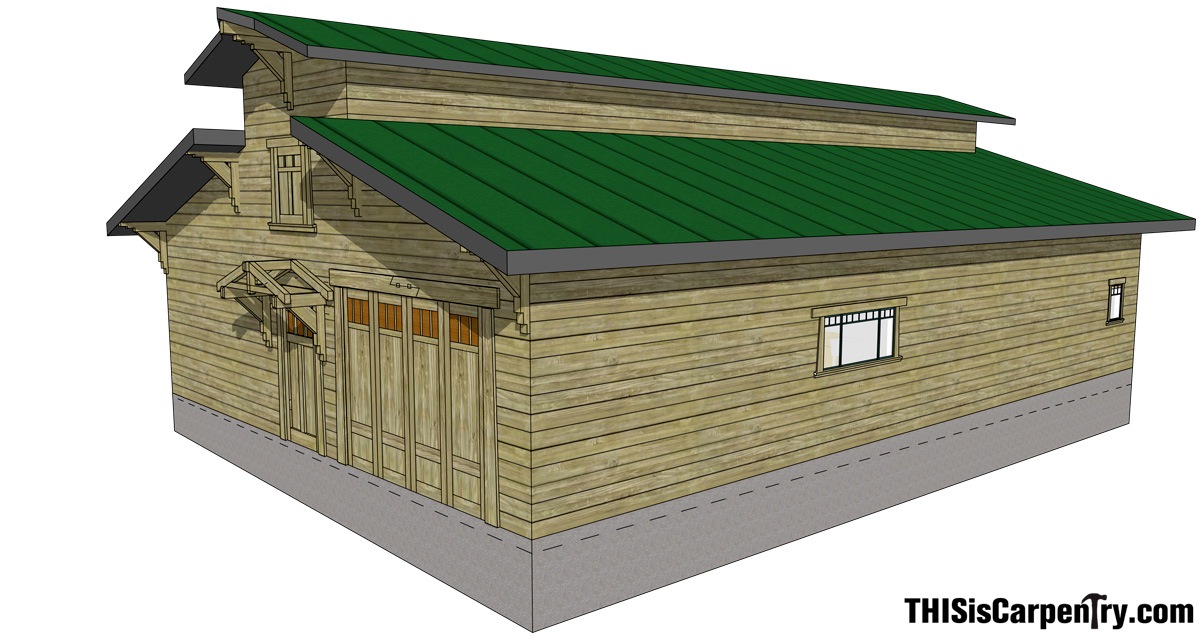
When Gary Katz asked me to build a new shop for him I figured I was up for the task. The plans showed it was really just a big rectangular barn with a simple gable roof and a 4/12 pitch. The rendering showed a prow feature on the upper overhang at each end of the building, but the elevation showed a standard two-foot overhang. I could’ve worried about the discrepancy at the time, but I had a lot of work to do and wasn’t going to be dealing with that feature for months. After all, we hadn’t even broken ground yet, and I had many more pressing concerns
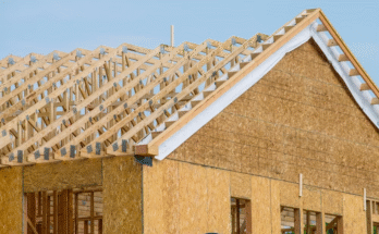
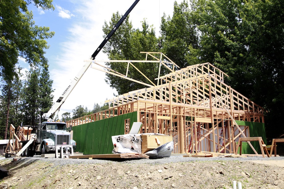
Two months later, with the trusses installed, it was time to construct the overhangs and sheet this box. And it was time to get to the bottom of this prow design. After posing the question to Gary, he said, “I’ll tell you what: let’s make it easy. Just start the prow at your last outlooker and extend the ridge out an extra foot. Oh, and by the way, you’ll be installing non-structural WindsorONE fascia, so you’ll need to install sub-fascia as well. I want the raw sub-fascia surfaces of these overhangs double-primed—even the surfaces that will be covered. And, I want an air gap between the sub-fascia and the fascia.” …So much for easy. And it got a lot harder, too! With some clients, you have to just bite your tongue.
Layout
Like any project, I wanted to get these prows built correctly and completed in a timely fashion. However, this project had an extra element of pressure because of the client. Even when I don’t think he’s around, I can feel the guy watching over my shoulder the whole time. And, he’s got lots of cameras.
Miter Angles
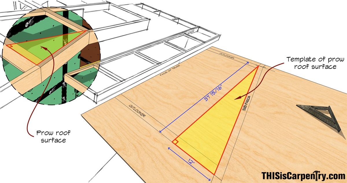
The first thing I did was create a full-scale plywood template of the roof surface of the prow.
I had already set the transition lookouts and taken my common rafter measurement of the distance between the transition lookouts and the center of the ridge on the south gable end of the building.

Since Gary told me to extend the ridge out an extra 12 inches, I simply plotted this on my plywood template.
I used a T-square to make it easy to plot all of these points and intersect lines on the template. I was able to measure the prow length for the sub-fascia, and then derive most of the required angles.
Plumb Cuts
The plumb cuts on the regular gable fascia were easy to determine—they were simply 18.5 degrees, with the 4/12 pitch of the main roof. The prow plumb cuts were a little more difficult to figure out. I am no mathematician or engineer, but since the overhang ridge is horizontal and the regular fascia is perpendicular to it, this situation is just a sequence of right triangles, and similar to a hip/valley rafter (irregular in this case). I used a regular calculator and the Pythagorean Theorem (a2 + b2 = c2) to calculate the unknown dimension of the triangle. I then plotted it out, and measured the angle for the prow plumb cuts. I also checked my math with a construction calculator, just for reassurance.
I knew the pitch of the regular roof (4/12) but I had to figure out the pitch of the prow, so I needed to find the horizontal run of the prow fascia to complete the equation.
My original plywood template of the roof surface gave me the “prow length” (39 13/16 in.), which was the diagonal or hypotenuse of the triangle, and I also knew the vertical “rise.” This allowed me to determine the prow “run” using the Pythagorean Theorem. The prow length was the “c” in the equation and “a” was the rise. I knew the rise was 12 in. because the common run of the prow was 36 in. Since the pitch of the main roof was 4/12 (4 in. of rise for every 12 in. of run), and 3 x 4 in. = 12 in. So: 12 in.2 + b2 = 39.8 in.2.
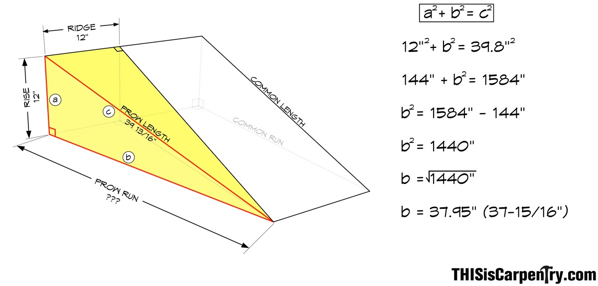
Back at the template I laid out the 3 points on a square corner of the plywood and used my speed square to determine the pitch angle of the prow sub-fascia: about 17 degrees.
The regular gable sub-fascia is pitched at 18.5 degrees, and the prow is a 17.5 degree pitch. Pretty close. The very small difference in pitch makes the length of the mitered plumb cuts very close to one another.
Of course, everything lays out perfectly when you’re drawing on a piece of plywood and using a calculator while standing on the ground. But we all know that’s not the real world—it never works that way when you’re up twenty feet in the air with a circular saw. I took into account that some angles and cuts of the actual sub-fascia and fascia would need to be modified—after all, even the trusses and lookout framing isn’t perfect. I made sure to leave all of the sub-fascia pieces a little long so I could afford to recut something if I had to.
On the Ground
The first order of business was to fabricate the ridge lookout while I was still on the ground.
Satisfied with the mock up, I cut the prow tip on each half of the ridge lookout on the miter saw by placing the bevel cut against the fence to simulate their finished position on the roof.
Then I swung the saw to the opposite 18.5-degree miter angle to cut the other half of the ridge. Cutting the ridge pieces “in position” on the miter saw was a critical step, because it provided the slight bevel angle (just under 6 degrees) that the lookouts needed in order to keep the prow fascia plumb.
In the Air
I knew I’d be on those gable ends for a while, so I built a working platform for each one. I needed the platforms to build the overhangs and to help make the painting easier, too.
Installing all of the outlookers was easy because I had asked the truss manufacturer to build dropped top chord trusses for the two gable ends. I asked him to drop the top chord an inch and a half (the thickness of my outlooker lumber). This way I didn’t have to cut notches in the top chords of the trusses for all of the outlookers.
When I install outlookers, I always attempt to install them perpendicular to the gable end truss using my framing square. For these prow overhangs, I went the extra mile and used a framing square knowing that every little thing that I could do to make the overhang framing as perfect as possible would pay off when I started cutting the transition outlookers and installing the sub-fascia.
Next, I cut the transition outlookers to match my plywood template. I wanted the gable fascia to transition into the prow fascia in the middle of the outlooker so that the outlooker could support both pieces of sub-fascia.
With the sub-fascia on the eave overhangs cut to length, it was now time to cut and install the sub-fascia on the gable end. I precut the transition angles on the four pieces of sub-fascia on the ground using the plumb cuts and miter angles I had figured out earlier—leaving all the pieces long and hoping for the best. I started on the right side with the first piece of normal raked sub-fascia. Letting the extra length of the board run past the eave, I slid the sub-fascia into position on the transition outlooker and screwed it at both locations.
While adjusting the fit of the sub-fascia at the transition outlooker, I was careful to keep the prow piece in plane at the ridge. If it didn’t plane in correctly, the miter and bevel at the transition would open.
Installing the Fascia
We used WindsorONE 2×8 fascia. I was glad that I did my homework when I installed the sub-fascia because it made installing the fascia a breeze. I wanted to work my way up and down the fascia in the same order as the sub-fascia. I cut some fascia scrap into 18-in. long mock-up blocks and used the same miter and bevel angles as I had used on the sub-fascia. This helped me pinpoint the intersections of the fascia. I held the mock-up blocks against the sub-fascia to check the joinery and make any final adjustments to the angle cuts. I temporarily installed each piece of fascia until I had all three fascia intersections fitting perfectly. Then, I removed the fascia and stapled on strips of home slicker that I had precut to 5 inches wide.
The home slicker provides a quarter-inch gap between the sub-fascia and the fascia, which allows any moisture—either from the moisture content of the wood or from the air—to drain and dry out.
Finally, I nailed on the fascia permanently for the last time, cut the tails at the eaves, and told the painter not to screw it up.
In the end, these were fairly simple prows to frame in comparison to others. The sub-fascia was the key to this project. I knew if I dialed in the sub-fascia, the fascia would be much simpler. And it was. I used KD fir 2×6 for the sub-fascia. I made mistakes with that material instead of the WindsorONE. I’m not going to lie to you: about half of the prow sub-fascia pieces worked on the first try, and the other half had to be “adjusted” using the old hunt-and-peck system, which a few times required several cuts up on the working platform using a circular saw. That is why I left the pieces long to start with.
Writing this article forced me to really think about the best, fastest, and most accurate ways to tackle installing prow fascia, and it seems like there are a lot of potential pitfalls. For starters, there must be hundreds of different potential prow angles and pitches. Each prow gable could present a whole new set of calculations. I consider myself to be a bit of a perfectionist, but in my experience, it’s very rare to frame a 20-foot tall structure and have the rooftop components perfectly level, square, or straight, which is what you need to calculate and pre-cut prow fascia. Math and geometry on paper (or plywood) are basically perfect. But in the real world, even the slightest error in a prow fascia cut or angle, a crowned gable end rafter, or a slightly cupped fascia board can leave your miters and bevels open. And to make matters more difficult, most of us are cutting fascia with pencil lines marked with a framing pencil and a speed square, and we’re making a compound miter cut with a circular saw. Prow fascia should be cut using a miter saw.
The Whole Story
Some of you with sharp eyes may have noticed that some of the photos showed a slightly different approach. Here’s why:
After the sub-fascia was completed on the south gable of the shop, I set up my platform on the north side of the shop. Like I said before, the first time you do something it always takes longer, but the second time is always easier and faster. I was pretty excited to take what I’d learned from the south side of the shop and put it to work on the north side.
That’s when Gary walks up and says: “Hey, Scott, I’ve got an idea…”
By that point, I’d been working with Gary for over six months and I’d learned to fear that phrase, with good reason. He said, in the kindest voice, and as if it wouldn’t be any problem:
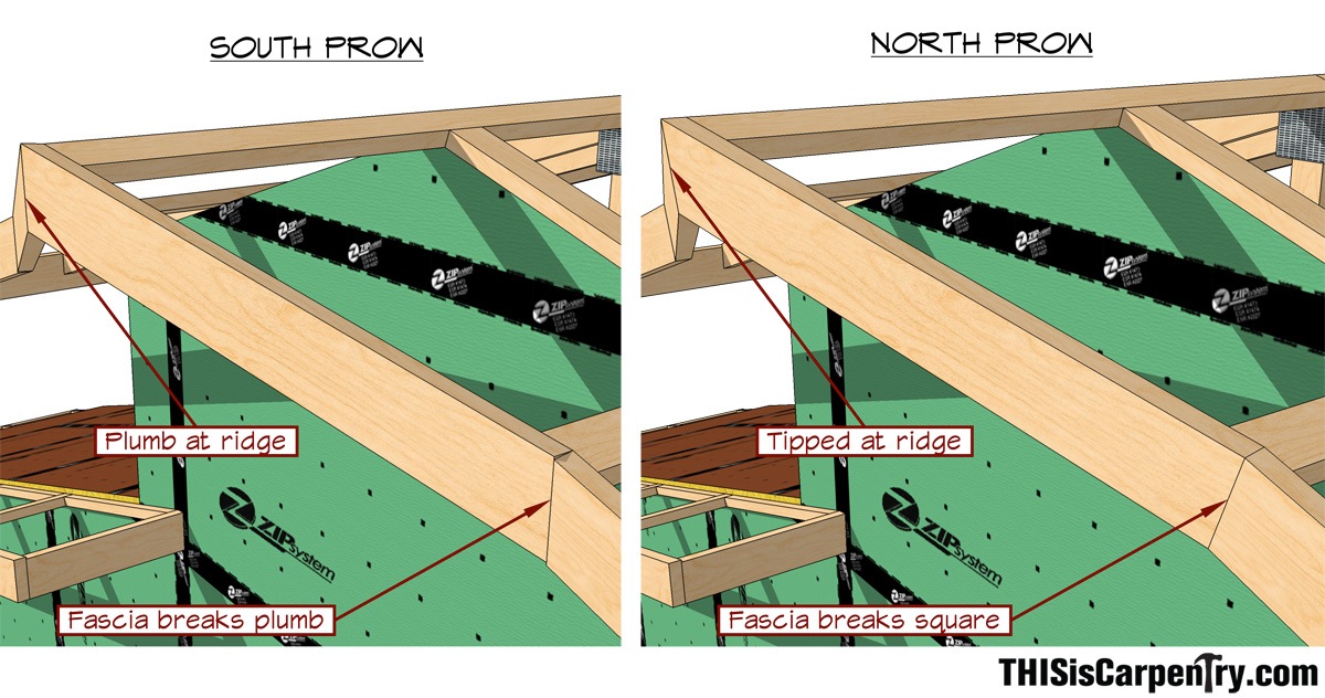
“Could you frame the prow on this end a little different? I want you to frame this end so the fascia transition to prow breaks square instead of plumb. So the peak of the prow tips out away from the building. And you’re taking good notes, right? I’m going to need you to write an article about both of these methods.”
Right! On both counts. Just when I’ve got it figured out, the “client” throws me a curve ball. After careful consideration (was it time to walk off the job?), I realized that I really didn’t know how to calculate the miters and bevels at all—there was nothing to go by.
I started by cutting the ridge outlooker ends without a bevel, which forced the fascia to tip out of plumb about 6 degrees. I knew the transition outlooker wouldn’t need a bevel either—it was just a simple inside corner miter—and I could precut those ends of the sub-fascia. However, pre-determining the miter and bevel angles at the ridge was a total mystery.
Installing the actual fascia was much easier because I had taken my lumps on the sub-fascia and I used the same method of mock-up blocks that I used on the south end of the shop.
After I finished with the prow gables, I reviewed my notes on the finished bevels and miters. I had a hard time detecting a relationship between the two methods. And I still don’t know how to figure out the miters and bevels of intersecting tipped-prow fascia. I am sure that there are carpenters out there with more experience in this than me (Sim, are you there?). I also can’t think of many other parallels to this aspect of framing except for angled and raked balloon-framed walls, which present a similar problem. Of course, being proficient with SketchUp would help determine these miters and bevels. But I didn’t speak with Todd Murdock until after this job was done!