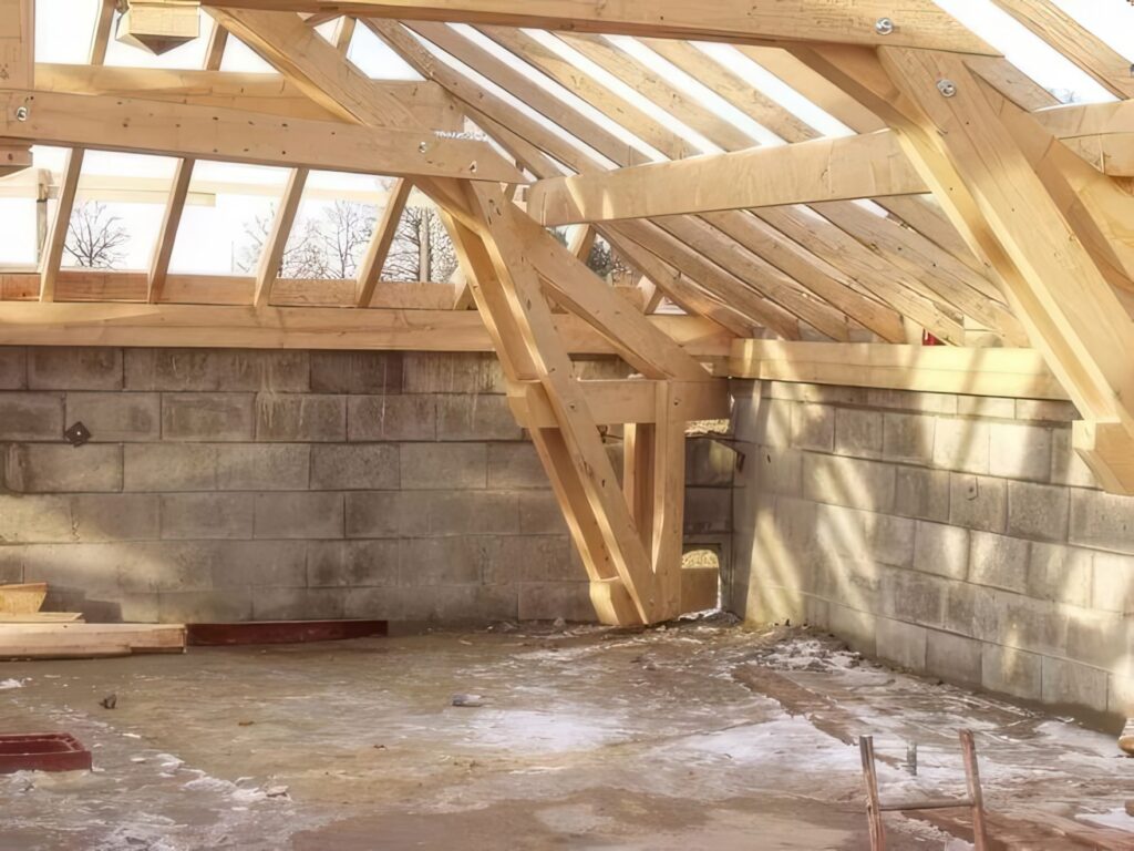
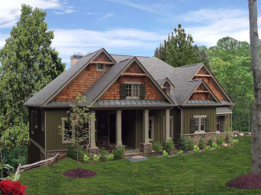
In the intricate symphony of building construction, where countless elements converge to create shelter and form, the roof framing plan holds a position of fundamental importance. Far more than a simple sketch, it is the meticulously crafted, scaled layout or diagram that precisely details the proposed roof development for a structure. This essential document serves as the definitive guide for builders, engineers, and inspectors, translating architectural vision into the tangible bones that will support the roof’s weight, withstand environmental forces, and define the space below. It is the engineered roadmap for everything above the top plate.

Deconstructing the Plan: What It Is and What It Shows
At its core, a roof framing plan is a specialized architectural or structural engineering drawing. It presents a top-down view of the entire roof structure, as if looking down from directly above after removing all roofing materials, sheathing, and ceiling finishes. Crucially, this view is drawn to a specific scale (e.g., 1/4″ = 1′-0″, 1:50), allowing accurate measurement and understanding of dimensions, spacing, and relationships between components. This scaling is non-negotiable; it ensures the plan can be reliably used for material take-offs, fabrication, and on-site construction.
The plan functions as a detailed diagram, employing standardized symbols, line types, and annotations to represent the complex three-dimensional framework in two dimensions. Key elements it meticulously illustrates include:

- Primary Structural Members:
- Rafters/Trusses: The principal sloping members carrying the roof load down to the walls. The plan shows their direction, spacing (e.g., 16″ or 24″ on center), size (e.g., 2×8, 2×10), and type (common rafter, hip rafter, valley rafter, jack rafter). Trusses are shown as single lines with specific labels indicating their type and location.
- Ridge Beam/Board: The horizontal member at the peak where opposing rafters meet. Its size, species (if timber), and support points (posts or bearing walls below) are clearly indicated.
- Hips and Valleys: The diagonal lines formed where different roof planes intersect. The plan details the members framing these critical junctions (hip rafters, valley rafters, jack rafters).
- Ceiling Joists/Roof Ties: Horizontal members spanning between opposing walls or rafters, resisting outward thrust and providing a platform for ceiling finishes. Their size, spacing, direction, and connection points are specified.
- Collars Ties/Purlins: Additional members shown if used for bracing or support (collar ties higher up in the rafter pairs, purlins running perpendicular to rafters).
- Supports and Connections:
- Load-Bearing Walls: The walls below that carry the roof load are clearly identified, often with specific notes or symbols.
- Beams (Headers, Girders): Any beams supporting rafters, trusses, or other framing members (e.g., over large openings or carrying points where walls don’t align below) are shown with their size, material, and bearing locations.
- Posts/Columns: Structural posts supporting beams or ridge points are located and sized.
- Connection Details: While detailed connection drawings might be separate, the framing plan often references standard details (e.g., “Rafter to Plate Connection – See Detail 5/A3”) or uses symbols indicating specific fastening requirements (nails, bolts, hurricane ties, joist hangers).
- Dimensions and Layout:
- Overall Dimensions: Critical overall lengths and widths of the roof structure.
- Member Spacing: Exact spacing between rafters, trusses, ceiling joists, etc.
- Locations: Precise positioning of hips, valleys, dormers, chimneys, skylights, vent stacks, and any roof penetrations relative to the framing grid.
- Overhangs/Eaves: Dimensions for rafter tails or lookout extensions creating the roof overhang at eaves and rakes.
- Annotations and References:
- Callouts: Text notes specifying member sizes, materials (e.g., “SPF No.2”, “LVL 1.75″x11.25″”), grades, specific connection hardware, or special instructions.
- Section References: Indicators (like “Section A-A”) pointing to related cross-sectional drawings showing the vertical relationships and details.
- Detail References: Links to enlarged drawings showing complex connections or specific conditions.
- Symbols Legend: Explanation of any specialized symbols used on the plan.
- General Notes: Important specifications regarding materials, construction standards (e.g., building code references), tolerances, bearing requirements, and design loads (e.g., ground snow load, wind speed).
The Critical Purpose: Why a Roof Framing Plan is Indispensable
The creation and use of a roof framing plan are not mere formalities; they are essential for numerous reasons:
- Design Communication & Coordination: It is the primary communication tool between the architect/designer, structural engineer, and the construction team (contractor, framers). It ensures everyone involved has the same, unambiguous understanding of the roof’s structural intent and configuration. It coordinates with underlying wall framing and foundation plans.
- Structural Integrity & Safety: The plan embodies the structural engineering calculations. It dictates member sizes, spacing, and connections specifically chosen to safely carry dead loads (weight of the roof itself), live loads (snow, maintenance personnel), and environmental loads (wind, seismic forces) down to the foundation. Deviating without engineering approval risks catastrophic failure.
- Accurate Material Estimation and Ordering: Contractors rely on the scaled plan and its annotations to perform precise material take-offs. They can calculate the linear footage of lumber, number of trusses, sheets of sheathing, and specific hardware (hangers, straps, fasteners) needed, preventing costly shortages or wasteful over-ordering.
- Efficient Construction & Layout: The plan is the framer’s step-by-step guide. It shows exactly where every rafter, truss, beam, and post needs to be placed. This allows for efficient layout on the top plates, accurate cutting (especially for complex angles on hips/valleys/jacks), and systematic assembly. It minimizes errors and rework.
- Compliance with Building Codes: Building inspectors use the approved framing plan to verify that the constructed roof complies with the relevant building codes and engineering specifications before sheathing is applied. It serves as a legal document demonstrating adherence to safety standards.
- Clash Detection: A well-coordinated framing plan helps identify potential conflicts before construction begins – for example, a large ductwork run interfering with a structural beam, or a chimney positioned where it conflicts with a major rafter.
The Genesis: Creating the Roof Framing Plan
Developing a roof framing plan is a collaborative and technical process:
- Architectural Input: The architect provides the basic roof design – shape (gable, hip, gambrel, shed, complex), pitch (slope), overhangs, and locations of dormers, skylights, etc. – typically on the roof plan within the architectural drawings.
- Structural Engineering: The structural engineer takes the architectural design and determines the loads the roof must carry. They then calculate the required sizes, species, and grades for all framing members (rafters, beams, ridge, joists, ties), their spacing, and the necessary connections to safely transfer these loads. They define the structural logic.
- Drafting/Modeling: Using CAD (Computer-Aided Design) or BIM (Building Information Modeling) software, drafters or technologists create the scaled plan view. They translate the engineer’s specifications and the architect’s design into the precise diagrammatic layout, using appropriate line weights, symbols, and annotations. BIM models offer the added advantage of intelligent 3D components and automated clash detection.
- Coordination & Review: The draft plan is rigorously reviewed by the engineer and architect to ensure accuracy, completeness, and coordination with all other disciplines (mechanical, electrical, plumbing for penetrations). Revisions are made as needed.
- Approval & Issuance: The finalized plan is stamped by the responsible structural engineer (a legal requirement in most jurisdictions) and issued as part of the permit and construction drawing set.
Conclusion: The Backbone Above
A roof framing plan is far more than lines on paper or pixels on a screen. It is the engineered crystallization of a proposed roof development. As a scaled layout and diagram, it meticulously details the skeleton that will define the building’s uppermost enclosure. It ensures structural soundness, enables accurate costing and procurement, guides efficient construction, facilitates regulatory approval, and ultimately safeguards the integrity of the entire structure and the people within it. Without this critical blueprint, the complex task of raising a safe, durable, and well-constructed roof would be fraught with uncertainty, inefficiency, and unacceptable risk. It is the indispensable backbone upon which the protective shell of a building is reliably built.


